GPS Waypoint Navigation and Obstacle Avoidance
August – December 2022
Objective: To navigate the ECHO Penguin robot through GPS waypoints while avoiding obstacles
Tools and Resources:
- Clearpath Husky
- Ubuntu 20.04 with ROS2 foxy
- Velodyne VLP-16 LiDAR
- Ricoh Theta 360 camera
- ZED2 depth camera
- GPS and IMU sensors
- Gazebo Simulation
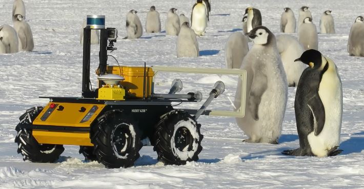
Details: While working in the Marine Animal Remote Sensing (MARS) Laboratory at the Woods Hole Oceanographic Institution (WHOI) on the ECHO Penguin robot, we wanted the robot to move from its current location through a set of defined waypoints. It is required because the temperature in Antarctica is freezing cold and it is very difficult to manually control the robot using a joystick. Another factor is that as the robot moves away from the operator, it appears small in size and thus, the operator finds it difficult to navigate. I tried to look for some ROS packages which could be handy but could not find any straightforward solution. So, I made my own package that can navigate the robot through waypoints. The packages were first tested in different Gazebo simulation environments and then on the real robot.
The custom_nav_stack_pkg has two scripts:
mode_control.py: It listens to the Joystick, IMU, and GPS ROS messages and defines a particular mode of operation. It does so with the help ofmessage_filters.ApproximateTimeSynchronizer. Different modes of operation are activated when a specific combination of buttons is pressed on the joystick.- E-STOP: It can stop the robot instantly (Emergency Stop) and override all manual joystick/ automation script commands
- GPS: The robot will try to follow the GPS waypoints until the destination is reached without worrying about any obstacles in the path
- Local: The robot will try to avoid the obstacle by moving around it
- Auto: The robot will try to follow the GPS waypoints while avoiding the obstacles as well
- Manual: The robot will listen to the operator’s input through the joystick irrespective of the commands given by the automation scripts.
How does the robot know its heading?
To answer this question, I first tried to calculate it using a magnetometer but it was not giving stable values. First, drive the robot in a circle for 2-3 times. Record the magnetometer readings and calculate the calibration parameters (https://digilent.com/blog/how-to-convert-magnetometer-data-into-compass-heading/, https://www.fierceelectronics.com/components/compensating-for-tilt-hard-iron-and-soft-iron-effects), store them and use for further data from mag sensor Even when the robot was static, the calculated heading value fluctuated a lot. Moreover, the earth’s magnetic field keeps on changing from time to time. It is not an accurate measurement but is based on models (https://www.ngdc.noaa.gov/geomag/calculators/magcalc.shtml). So, this approach was dropped.
Then, I used something similar to how the navigation apps like Google Maps use to find the heading (although in a simplified form). When the robot boots up, it does not know its heading but knows its current location (latitude/ longitude). Then, let the robot stay in this location for 10 seconds to find the mean location as GPS measurements are noisy. It then moves forward for 20 seconds (can hit obstacles during this period until E-STOP is used) and calculates the average at the new location. Now, that we know two sets of latitude/ longitude, we find the robot’s heading using the formula provided here. As the robot changes its heading, a new heading value can be found by taking into account the IMU readings. Given the waypoints, we can also calculate the required bearing and try to align the robot in that direction.
The script also calculates the distance between the robot’s current location and the next GPS waypoint in meters using Geodesic WGS84 (code adapted from the gps_goal ROS package) and reports them to a log file. These distance calculations turned out to be good enough for our application.
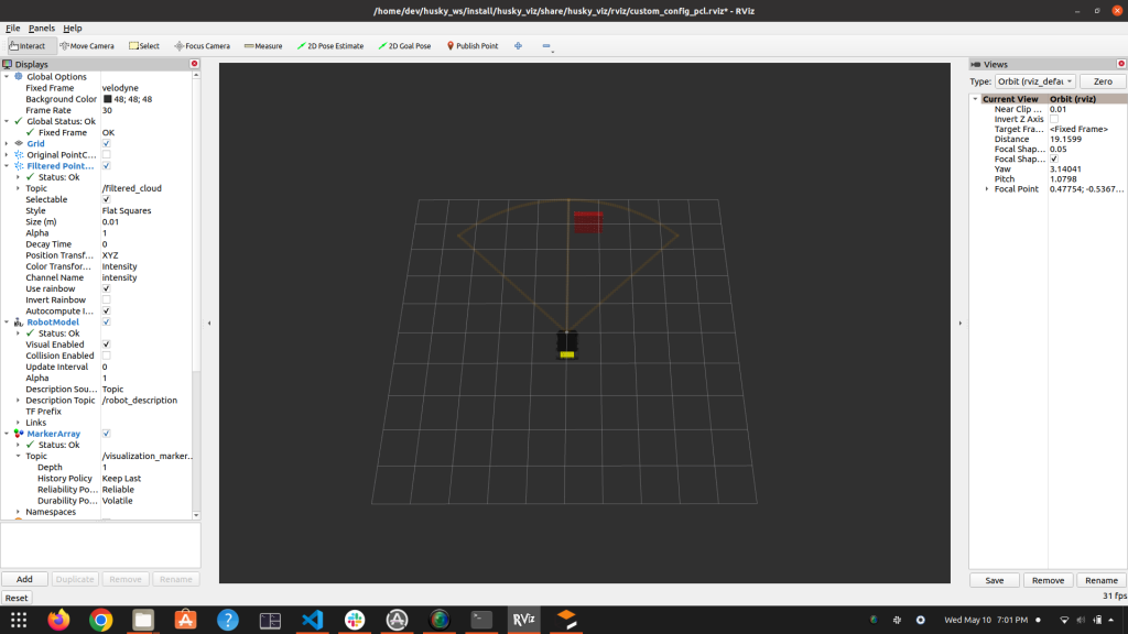
- To detect obstacles, the point cloud is processed using the Point Cloud Library (PCL). Code is written in
lidar_cpp_node.cpp
Steps followed:
- Convert the
sensor_msgs/PointCloud2data topcl/PointCloud - Filtering Using VoxelGrid (Ref: https://codediversion.wordpress.com/2019/01/16/simple-ros-c-and-lidar-with-pcl-on-ubuntu-16-04/)
- Cropping Using CropBox (Ref: https://answers.ros.org/question/318183/how-to-use-cropbox-on-pointcloud2/)
- Segmentation Using RANSAC Algorithm
- Extracting non-ground points
- Clustering using K-D tree
Once we get a cluster (obstacle), a 3D Axis Aligned Bounding Box (AABB) or a cuboid is formed around it. Then, it is checked whether this AABB lies in the field of view of the robot using a function detect_obstacle. The basic idea behind this function is to check if a rectangle overlaps with a circular arc using simple geometry. The space is divided into different areas such as the rectangle in front of the arc, back, left, right, partially overlapping, etc.) I believe I have captured all the different possible scenarios in this function. Though, always open to feedback.
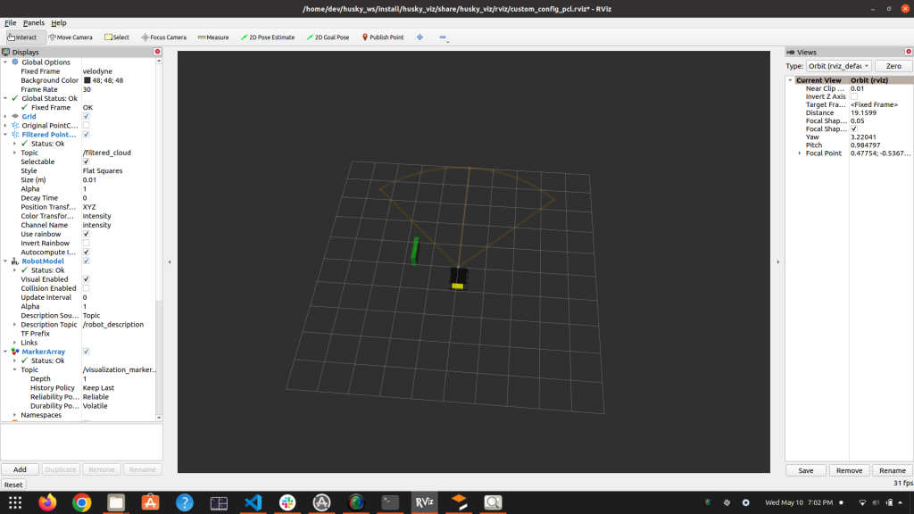
Once we know that the obstacle is present inside the robot’s field of view, its centroid location (angle from the robot’s heading) is provided to the Python script using Inter-Process Communication (IPC) and the robot will try to avoid it by moving the other way around.
Although, there is a limitation, viz. If the object is too close to the LiDAR, it won’t appear in the point cloud or might come partially only because of the sensor’s limitation to not show points that are very close to it.
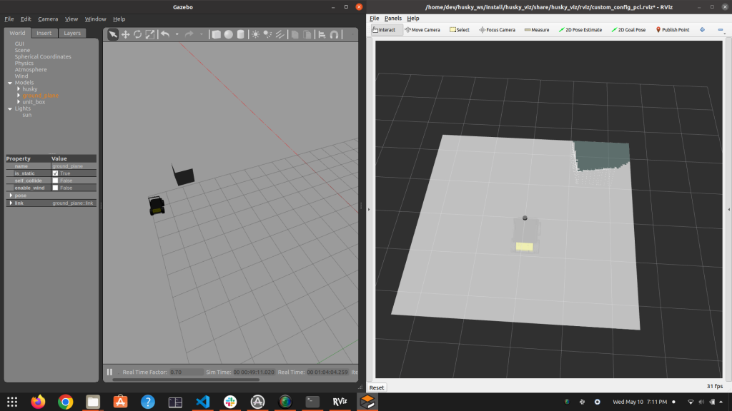
Path Planning using Occupancy Grid and a planner
I tried looking for a package that could generate an occupancy grid from PointCloud but could not find any. However, I came across one work workaround by first converting the 3D point cloud to a 2D laser scan message and then using Bresenham’s line algorithm in all quadrants to generate the occupancy grid. occupancy_grid_generator.cpp does this job. It also handles those grids which are occluded by the obstacles by assigning them -1. A free cell is indicated by 0 and occupied by 1. Probabilities are not assigned to keep the implementation simple. Implemented and verified.
The next step is to use this occupancy grid and path planner (RRT/ RRT*/ other) from OMPL and try to avoid the obstacle. I believe this is a more robust way to avoid obstacles than the naive approach to moving around the obstacle which does not guarantee success. This part is still to be implemented.
Github repo link: https://github.com/devvaibhav455/husky_foxy/tree/main/custom_nav_stack_pkg