Electronic Toy Piano using 555 Timer IC
November 2015
Motivation: It was our first project in college and we wanted to make something related to music and technology.
Objective: To make a toy piano that produces sounds of various frequencies.
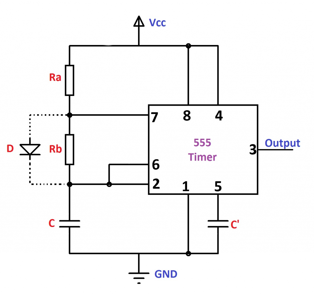
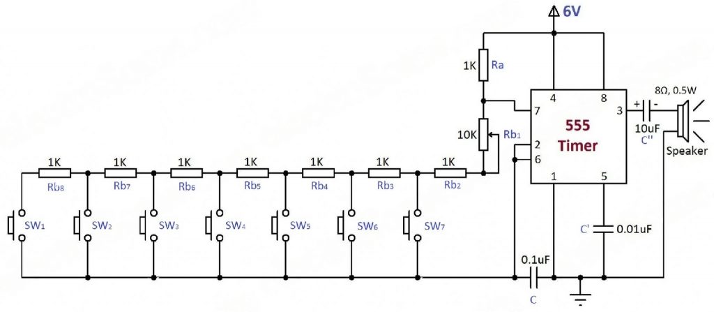
Details: We were a team of four and we used an array of switches and resistors along with 555 Timer IC operating in astable multivibrator mode to vary the output signal frequency of the circuit. When used in the astable mode both the frequency and duty cycle of the output waveform can be accurately controlled to produce a very versatile waveform generator. This signal was fed to the buzzer which produced sound corresponding to the frequency that is fed to it. Resistors of suitable value can be used accordingly to produce frequencies corresponding to Sa-re-ga-ma-pa. This project was a blend of art and technology. At this time, we did not know the way to make this using CAD tools as it was our first electronics project in college. So, we made the design on butter paper using a marker and ruler and did the whole process manually. It enabled us to gain basic knowledge of electronics circuits and IC operation.
References: https://www.electronics-tutorials.ws/waveforms/555_timer.html, https://electrosome.com/electronic-piano-555-timer/